Dejar un mensaje
Si le interesan nuestros productos y desea obtener más información, deje un mensaje aquí y le responderemos lo antes posible.

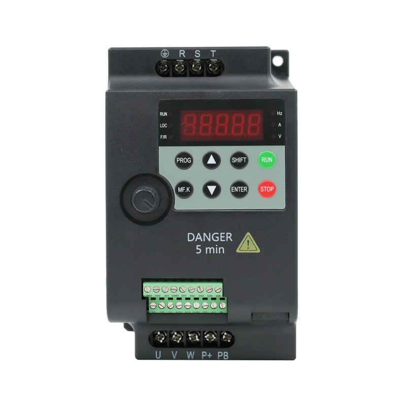
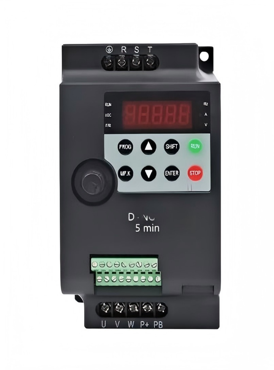
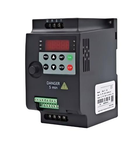
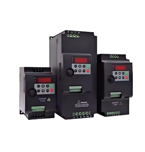
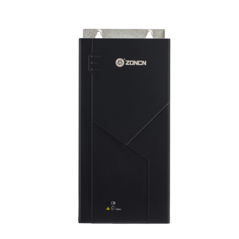
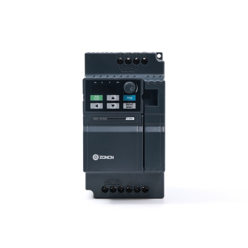
La serie H2000 es un variador de frecuencia de bajo costo especialmente diseñado para aplicaciones de baja potencia.
Número de artículo :
H2000Pedido (cantidad mínima de pedido) :
20Pago :
Paypal/TT/Western UnionOrigen del producto :
Shanghai, ChinaColor :
BlackPlazo de entrega :
18-30 daysPeso :
8.5kgEste variador de frecuencia de bajo coste está especialmente diseñado para aplicaciones de baja potencia. Presenta la misma apariencia y funcionalidad que la serie Delta L, incluyendo una curva V/F ajustable, una frecuencia portadora de hasta 10 kHz, compensación automática de par y deslizamiento, Modbus (RS485) integrado y un filtro EMI incorporado.
Características del producto
Especificaciones técnicas
Artículo | Especificación H2000 |
Voltaje de entrada | Soltero Fase tres Fase 200-240V,Tres Fase 380~440V Fluctuar no más quen±10% ,Desequilibrio Tasa <3%. |
Aporte Frecuencia | 50/60 Hz ± 5% |
Voltaje de salida | Voltaje de entrada de 0 V~ |
Producción Frecuencia | Control vectorial: 0~300 Hz Control V/F: 0~3200 Hz |
Actuación | |
Capacidad de sobrecarga | 150% corriente de salida nominal para 1 minuto, 180%corriente de salida nominalt para 2 artículos de segunda clase. |
Control Método | Control vectorial de lazo abierto (SVC), V/Fcontrol |
Ejecutar comando Configuración Método | Operación Configuración del panel, Externo Terminal Entorno, Comunicación Configuración. |
Ajuste de velocidad Método | Configuración digital, configuración analógica/pajuste de pulso, configuración de comunicación. |
Ajuste de velocidad Resolución | Ajuste digital: 0,01 Hz, Configuración analógica: 1% × frecuencia máxima |
Control de velocidad Exactitud | SVC: ±0,5% |
Control de velocidad Rango | SVC: 1:100 |
Control de par Respuesta | SVC: <200 ms |
Par de arranque | SVC: 150 % del par nominal/0,5 Hz |
Especial Característica | |
Programable Aporte & Terminales de salida | Terminal de entrada y salidaLa función l puede ser editado |
Proceso PID Ajuste Función | Incorporado proceso PID módulo |
Simple SOCIEDAD ANÓNIMA Función | Integrado sencillo SOCIEDAD ANÓNIMA módulo, que puede realizarSincronización y salida de frecuencia multisegmentoponer. |
Oscilación textil Función | Frecuencia de oscilación textil incorporadafunción ncy módulo |
Función protectora | |
Bloqueo por sobretensión | Control automático de voltaje del bus prevenir encima falla de voltaje |
Corriente automática Limitación Protección | Corriente de salida es automáticolimitado omáticamente to prevenir fallas por sobrecorriente |
Sobrecarga Prealarma yAlarma | Sobrecarga Preaviso y protección |
Producción Fase Pérdida Protección | Producción detección automática de pérdida de fase y función de alarma |
Sobretensión y Desbordamiento Parar Control | Limita automáticamente la corriente y el voltaje. duranteoperación para evitar sobrecorrientes frecuentesnt y disparo por sobretensión |
Salida de cortocircuito a tierra Protección | Función de protección eficaz parasalida corta circuito a tierra |
Producción De fase a fase Cortocircuito Protección | Producción interfase cortacircuito t efectivo función de protección |
Aporte & Producción | |
Analógico externo fuerza suministrar | +10V ,capacidad de carga 100 mA |
Digital externo fuerza suministrar | +24V ,Capacidad de carga 200 mA |
Cosa análoga Aporte | AI1: Voltaje 0~10V/0-20mA |
Salida de voltaje analógica | AOV: 0~10V |
Corriente analógica Producción | AOI: 0~20mA |
Digital Aporte | DI1~DI5 (DI5 puede be selecciónTed as a alto- pulso de velocidad señal) |
Salida digital | FM: FM puede ser seleccionado como alta frecuenciafrecuencia Salida de señal de pulso |
Salida de relé | TA/TB/TC: Contacto Clasificación 250 VCA/3Un o 30 V CC/1 A |
MODBUS Comunicación | A+、B- |
Operación Mostrar | |
CONDUJO Mostrar | Frecuencia de ajuste, frecuencia de salida, salida voltaje, corriente de salida, velocidad del motornecesidad, salidapar, terminales digitales, parámetro de estadoers,parámetros del menú de programación y culpa códigos etc. |
Indicador Luz | 3 unidades indicadores, 3 estados indicadores. |
Características ambientales | |
Temperatura de funcionamiento | -10~+40°C, temperatura máximaLa temperatura es de 50°C, Cambio de temperatura del aire es menor que 0,5 °C/min, 40~50 °C La reducción de potencia es requerido, reducción de corriente de salida del 2% para cada 1°C. |
Almacenamiento Ambiente Temperatura | -40~+70°C |
Solicitud | Interior, libre de luz solar directa y polvo. gas corrosivo, gas inflamable,aceite niebla, agua vapor, goteo de agua o sal etc. |
Altitud | Menos que 1000 metros, declasificación is requerido por más de 1000 asignarrs. |
Humedad | Menos del 95% de humedad relativa, no condensación |
Resistencia a la vibración | 3,5 m/s² a 2~9 Hz, 10 m/s² a 9~200 Hz(IEC60721-3-3). |
Protección Grado | IP20 |
Contaminación Nivel | Clase 2 (Seco, polvo no conductor contaminación) |
Certificación | |
CE | Toda la serie tiene Certificación CE aprobada |
Accesorios opcionales | |
teclado | Toda la serie apoya exexterno tecladoa través de la red estándarorco cable |
Presupuesto
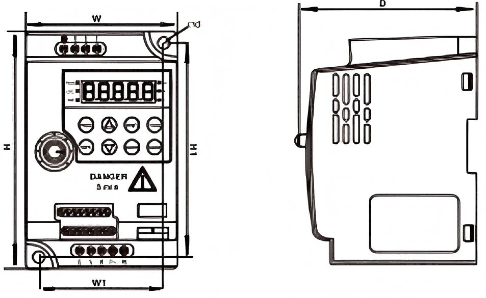
Modelo | Adaptable Motor (KW) | Aporte Actual (A) | Producción Actual (A) | Tasa Capacidad (kVA) | W (mm) | H (mm) | D (mm) | W1 (mm) | H1 (mm) | ΦD (mm) | GW (kg) |
| 1 Fase Entrada y 3 Fase Salidaut 220V (-15%~+15% de tolerancia) | |||||||||||
H2000-0R4G-2 | 0.40 | 6.50 | 2.10 | 0,70 |
85 |
142 |
116 |
73 |
136 |
5 |
1.0 |
H2000-0R75G-2 | 0,75 | 8.20 | 4.00 | 1.50 | |||||||
H2000-1R5G-2 | 1.50 | 14.0 | 7.00 | 3.00 | |||||||
H2000-2R2G-2 | 2.20 | 23.0 | 9.60 | 4.00 | |||||||
H2000-4RDG-2 | 4.00 | 39.0 | 16.5 | 5.90 | 106.5 | 240.5 | 148 | 96 | 230 | 3.0 | |
H2000-5R5G-2 | 5.50 | 60.0 | 25.0 | 8.50 | |||||||
| Entrada trifásica y salida trifásica de 220 V (tolerancia de -15 % a +15 %). | |||||||||||
H2000-4RDG-2 | 4.00 | 19.0 | 16.5 | 5.90 |
106.5 |
240.5 |
148 |
96 |
230 |
5 |
3.0 |
H2000-5R5G-2 | 5.50 | 28.0 | 25.0 | 8.50 | |||||||
H2000-7R5G-2 | 7.50 | 35.0 | 30.0 | 11.0 | |||||||
H2000-11G-2 | 11.0 | 47.0 | 45.0 | 16.0 | |||||||
Entrada trifásica y salida trifásica 380V(-15%~+15%Tolerancia) | |||||||||||
H2000-0R75G-4 | 0,75 | 3.40 | 2.10 | 1.50 |
85 |
142 |
116 |
73 |
136 |
5 |
1.0 |
H2000-1R5G-4 | 1.50 | 5.00 | 3.80 | 3.00 | |||||||
H2000-2R2G-4 | 2.20 | 5.80 | 5.10 | 4.00 | |||||||
H2000-4RDG-4 | 4.00 | 10.5 | 9.00 | 5.90 | 95 | 180 | 120 | 83 | 168 | 2.0 | |
H2000-5R5G-4 | 5.50 | 14.6 | 13.0 | 8.90 | |||||||
H2000-7R5G-4 | 7.50 | 19.0 | 17.0 | 11.0 |
106.5 |
240.5 |
148 |
96 |
230 |
3.0 | |
H2000-11G-4 | 11.0 | 28.0 | 25.0 | 16.0 | |||||||
H2000-15G-4 | 15.0 | 35.0 | 32.0 | 21.0 | |||||||
Diagrama de cableado típico
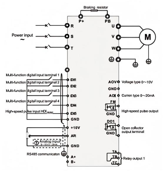
Nota:
Todos los inversores de la serie H2000 tienen el mismo método de cableado para el circuito de control.
La figura anterior muestra el diagrama de cableado del inversor trifásico de 380 V.
El terminal o representa el terminal del circuito principal, y representa el terminal del circuito de control.

Dejar un mensaje
Escanea y envíalo a WeChat. :

Escanea y envíalo a WhatsApp. :